MODBUS data structures
There are two possible solutions for this:
STATIC USHORT   usRegHoldingValue[3];

int
main( void )
{
    ...
    do
    {
        /* Poll the communication stack. */
        eMBSPoll( xMBSHdl );

        /* Update register values. */
        usRegHoldingValue[ 0 ] = usGetCurrentSensorValue(  );

        /* Read holding registers. */
        if( usRegHoldingValue[ 1 ] = 1 )
        {
            /* Value of holding register mapped at 0x0101 is now 1. */
            /* Turn on the control valve. */
            vSetValve( 1 );
        }
    }
    while( MB_ENOERR == eStatus );
    ...
}

eMBException
eMyRegHoldingCB( UBYTE * pubRegBuffer, USHORT usAddress, USHORT usNRegs, eMBSRegisterMode eRegMode )
{
    eMBException    eException = MB_PDU_EX_ILLEGAL_DATA_ADDRESS;
    STATIC const ULONG usRegsMappedAt = 0x0100;
    ULONG           usRegStart = usAddress;
    ULONG           usRegEnd = usAddress + usNRegs - 1;
    USHORT          usIndex;
    USHORT          usIndexEnd;

    if( ( usNRegs > 0 ) &&
        ( usRegStart >= usRegsMappedAt )
        && ( usRegEnd <= ( usRegsMappedAt + MB_UTILS_NARRSIZE( usRegHoldingValue ) ) ) )
    {
        usIndex = ( USHORT ) ( usRegStart - usRegsMappedAt );
        usIndexEnd = ( USHORT ) ( usRegEnd - usRegsMappedAt );
        switch ( eRegMode )
        {
        case MBS_REGISTER_WRITE:
            for( ; usIndex <= usIndexEnd; usIndex++ )
            {
                usRegHoldingValue[usIndex] = ( USHORT ) * pubRegBuffer++ << 8;
                usRegHoldingValue[usIndex] |= ( USHORT ) * pubRegBuffer++;
            }
            break;

        default:
        case MBS_REGISTER_READ:

            for( ; usIndex <= usIndexEnd; usIndex++ )
            {
                *pubRegBuffer++ = ( UBYTE ) ( usRegHoldingValue[usIndex] >> 8 );
                *pubRegBuffer++ = ( UBYTE ) ( usRegHoldingValue[usIndex] & 0xFF );
            }
            break;
        }
        eException = MB_PDU_EX_NONE;
    }
    return eException;
}
STATIC USHORT   usRegHoldingValue[3];

void
vTaskA( void )
{
    ...
    do
    {
        /* Poll the communication stack. */
        eMBSPoll( xMBSHdl );
    }
    while( MB_ENOERR == eStatus );
    ...
}

void
vTaskB( void )
{
    USHORT  usRegHoldingValueNew;
    BOOL    bTurnOnValve;
    do
    {
        ...
        /* Make the measurement first to not lock the stack for too long. */
        usRegHoldingValueNew = usGetCurrentSensorValue(  );
        MBP_ENTER_CRITICAL_SECTION(  );
        /* Update register values. */
        usRegHoldingValue[ 0 ] = usRegHoldingValueNew;

        /* Read holding registers. */
        if( usRegHoldingValue[ 1 ] = 1 )
        {
            /* Value of holding register mapped at 0x0101 is now 1. */
            /* Turn on the control valve. */
            bTurnOnValve = 1;
        }
        else
        {
            bTurnOnValve = 0;
        }
        MBP_EXIT_CRITICAL_SECTION(  );
        if( bTurnOnValve )
        {
            vSetValve( 1 );
        }
    } while( TRUE );
    ...
}

eMBException
eMyRegHoldingCB( UBYTE * pubRegBuffer, USHORT usAddress, USHORT usNRegs, eMBSRegisterMode eRegMode )
{
    eMBException    eException = MB_PDU_EX_ILLEGAL_DATA_ADDRESS;
    STATIC const ULONG usRegsMappedAt = 0x0100;
    ULONG           usRegStart = usAddress;
    ULONG           usRegEnd = usAddress + usNRegs - 1;
    USHORT          usIndex;
    USHORT          usIndexEnd;

    MBP_ENTER_CRITICAL_SECTION(  );
    if( ( usNRegs > 0 ) &&
        ( usRegStart >= usRegsMappedAt )
        && ( usRegEnd <= ( usRegsMappedAt + MB_UTILS_NARRSIZE( usRegHoldingValue ) ) ) )
    {
        usIndex = ( USHORT ) ( usRegStart - usRegsMappedAt );
        usIndexEnd = ( USHORT ) ( usRegEnd - usRegsMappedAt );
        switch ( eRegMode )
        {
        case MBS_REGISTER_WRITE:
            for( ; usIndex <= usIndexEnd; usIndex++ )
            {
                usRegHoldingValue[usIndex] = ( USHORT ) * pubRegBuffer++ << 8;
                usRegHoldingValue[usIndex] |= ( USHORT ) * pubRegBuffer++;
            }
            break;

        default:
        case MBS_REGISTER_READ:

            for( ; usIndex <= usIndexEnd; usIndex++ )
            {
                *pubRegBuffer++ = ( UBYTE ) ( usRegHoldingValue[usIndex] >> 8 );
                *pubRegBuffer++ = ( UBYTE ) ( usRegHoldingValue[usIndex] & 0xFF );
            }
            break;
        }
        eException = MB_PDU_EX_NONE;
    }
    MBP_EXIT_CRITICAL_SECTION(  );
    return eException;
}
void
vTaskA( void )
{
    xMQueueRegType_t xMsgRegs;
    do
    {
        /* Poll the communication stack. */
        eMBSPoll( xMBSHdl );
        /* Check if there are some messages in the message queue. */
        /* If yes process them and update the registers. */
        while( bGetMessageFromQueue( &xRegReadQueue, &xMsgRegs ) )
        {
            /* Now process xMsgRegs and update the global registers. */
        }
    }
    while( MB_ENOERR == eStatus );
}
For writing a message can be directly sent within the callback. For this case we would modify the eMyRegHoldingCB function as following. Please note that also here the function vSendMessageToQueue should be replaced with the correct function from your operating system.
eMBException
eMyRegHoldingCB( UBYTE * pubRegBuffer, USHORT usAddress, USHORT usNRegs, eMBSRegisterMode eRegMode )
{
    xMQueueRegType_t xMsgRegs;
    ...

    case MBS_REGISTER_WRITE:
        for( ; usIndex <= usIndexEnd; usIndex++ )
        {
            usRegHoldingValue[usIndex] = ( USHORT ) * pubRegBuffer++ << 8;
            usRegHoldingValue[usIndex] |= ( USHORT ) * pubRegBuffer++;

            /* Create a data structure and send it to the queue. */
            xMsgRegs.usRegAddress = usRegStart + usIndex;
            xMsgRegs.usRegValue = usRegHoldingValue[usIndex];
            vSendMessageToQueue( &xRegWriteQueue );
        }
    ...
}
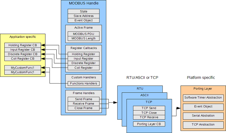
We can also see that the porting layers make use of a platform specific porting layer. This porting layer needs to be implemented once for your platform. The other information within the handles includes current state information, the slave address, an event object for signaling and the current active MODBUS frame if their is any.
MODBUS data structures
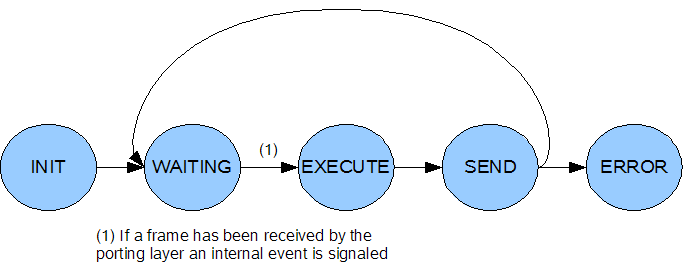
State diagram
WAITING state and waits for something interesting to happen by waiting on an event queue. Messages to the event queue are posted within the callbacks made by the porting layer. For example in the RTU/ASCII mode the serial porting layer is used. In the V1 API which is normally used on systems without an RTOS a callback is made to the stack whenever a new character is available. This character is then stored in an internal buffer and a timer is started and the call completes immediately. All callback functions have been kept very short because this makes processing very fast and therefore suitable for interrupt use. If no more characters are received within the timeout the stack will again get an callback from the timer module and will then post an internal event telling the main task to process this MODBUS frame. Again the reason is that processing the MODBUS frame within the callback is not possible. Now the main task awakes and will proceed to the EXECUTE state. In the executed state the frame is decoded and checked. If all tests pass callbacks are made to the application where the use must provide the actual register values. Then the stack proceeds to the SEND state. In the send state the response is assembled and passed to the frame implementation layers (RTU/ASCII or TCP). They now start to transmit the data using the porting layer. After transmission the stack goes back to the WAITING state. The ERROR state is reached when there are errors within the porting layer, for example if a serial interface is no longer available and the stack can not continue.